(GD&R)
An N-Scale Empire want-a-be
N-Scale The Normal Scale©

| Bench Work
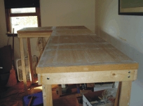
The bench work is what I call a box frame made of 1 X 4 pine and covered with 3/8 plywood. Cross braces are spaced periodically. The plywood is covered with 2X4 foot ceiling tiles with the unfinished side up. The edges of the ceiling tiles and plywood are covered with a 1/4 X 1 1/2 inch trim board, (local store calls it lattice). I paint the the ceiling tiles with a light brown paint before laying the roadbed. |
|
|
A view of the bench work From the bottom up I use the following for my bench work.
|
 |
|
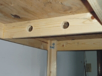 Showing a cross brace and leg attachment |
Legs are made of 1 X 2 and 1 X 3s screwed and glue to make an ell. A adjustable glide is mounted in the bottom of each leg. The legs are bolted to the box frame. To make things stable cross braces were added later. Since moving into the all steel building the 1 X 4s that are along the walls are screwed to the walls. | |
The image to the right shows the different sections of bench work as the current layout has developed since the earthquake of 2006 (See the History Page). The Grid lines are 12 inches apart.
|
||
As sections of bench work were added, they were either bolted or screwed to the section next to it. Legs are placed as needed to prevent sagging. It is amazing how much a 1 X 4 will sag in 4 feet. The top (yellow and orange) is 12 feet long. The left edge is 10 feet. At the right side of the image (above right) just below the orange, is the door to the "Train Building." The door is centered in the wall and open out. Next to the door are lighting controls and a window with an AC unitl. Due to a miss calculation (read - I Messed Up) while installing the AC unit, the bottom edge (Red) can not be extended to totally reach the end of the wall. |
||
| When comparing the track plan to the bench work you can get the idea how it all fits. | 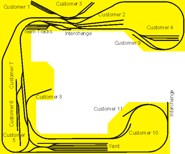 |
|
| Wiring
The layout is wired as one big block with 2 auto reversing sections, one at the Y near the yard and the other within the Brunk Industrial District. Each section of track between track switches is connected to the DCC controller. All of the track switches have insulated frogs and are power routed via the points. If a loco is on a section of track that the points are not aligned for that section the loco still has power. The track switches are not soldered to any of the track sections. This is because of my history of making changes I have ruined many track switches because I had soldered in place in the past. From the DCC controller the wiring goes through a Volt/Amp meter and then is divided into multiple runners at a junction block. These runners are 18 gauge 2 conductor stranded wires. To attach to the track a smaller feeder wire is soldered to the runners and then passed through the bench work and road bed and soldered to the rails. This may be overkill but I have not had any problems with sections of track dropping out and locos slowing down other then when the track is dirty. Speaking of dirty track |
||